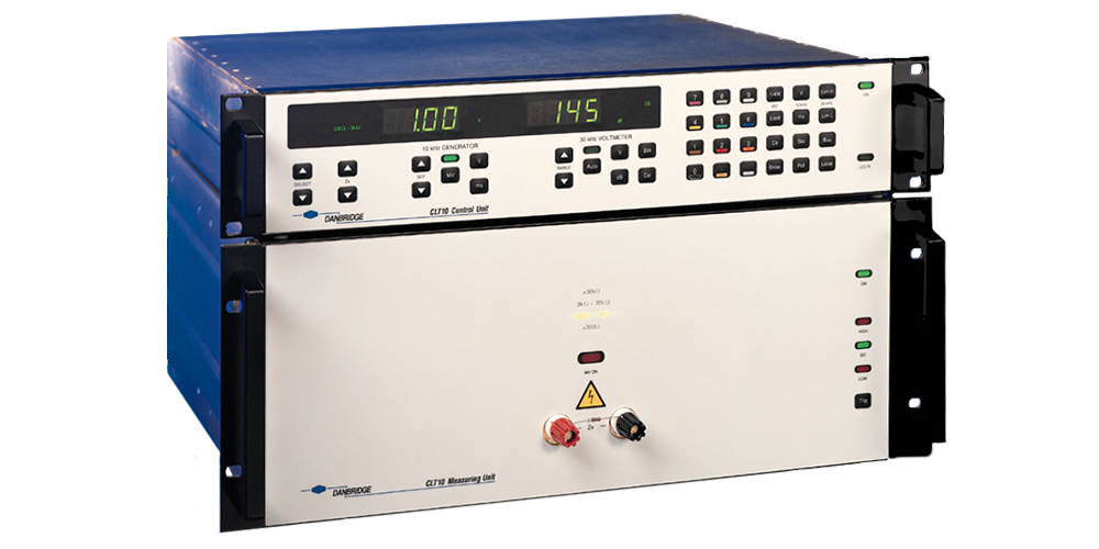
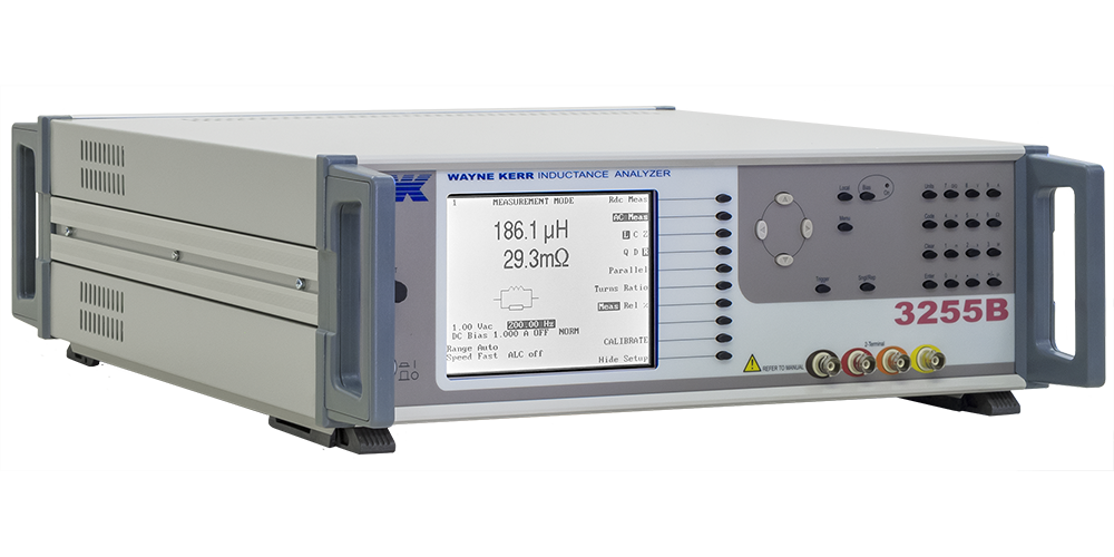
3255B SERIES

3255B SERIES INDUCTANCE ANALYZER


Overview
Completely characterize components with comprehensive parametric tests
The 3255B range of inductance analyzers are able to accurately characterise devices in a clear and simple manner. The inductance analyzers are available in three versions 3255BL (200kHz), 3255B (500kHz) and 3255BQ (1 MHz).
At the design stage of component development it is very important to analyse how components performs under different operating conditions. This includes operation over a range of frequencies, AC drive levels or DC bias currents.
The AC drive level can be set between 1 mV and 10 V. DC bias current can be set from 1 mA to 1 A internally (optional). Using the external 3265B range of DC Bias Units bias currents can be set to a maximum of 125 A.
Printed output of test results
Using the parallel Centronics interface the user can directly print all test results for further analysis and archiving.
In addition, via the optional GPIB interface, the instrument can be controlled from a PC and results can be read back for analysis and storage.
LabVIEW™ drivers are available on request or can be downloaded from the web site, www.waynekerrtest.com, providing a base from which a user can develop a specific test application.
Bin sort
The binning function allows component manufacturers to sort components in up to ten bins. Sorting is carried out either by absolute values or by percentage of values.
Component tests with up to 125 A DC bias current
The 3255B and 3255BQ enable components to be measured at up to 125 A when optional 3265B DC Bias Units are used. Extended DC bias capability is also available with the 3255BL which uses the 3265B/5A or 3265B/10A to extend the DC bias current available to a maximum of 50A.
Up to five of the DC Bias Units can be used in parallel to give a wide range of DC bias currents.
Internal DC bias is available as an option giving DC bias currents from 1 mA to 1 A.
The 3265B has a number of safety and protection features including a safety interlock system to protect users against back EMFs. It is also fully protected against over temperature, excess voltage drop and sense lead failure.
SMD inductor tests up to 50 A
With the addition of the 1009 DC Bias Fixture DC bias currents up to 50 A can be applied to an SMD inductor during component test in order to evaluate the devices thoroughly at operational bias currents. The fixture operates with one or two 3265B/25A Wayne Kerr DC bias units and a 3255B Inductance Analyzer. If two 3265B/25As are used then the optional 5-328-2005 high current lead set will be required.
Four rear panel mounted BNC connectors and two captive high current cables ensure simplicity and ease of use with a 3265B.
Interchangeable component test carriers ensure that the 1009 test fixture may be used with a wide variety of different devices. Blank carriers are available which enable device specific test fixtures to be developed or alternatively a carrier design and manufacturing service is available.
Stable component fixturing ensures high accuracy and repeatable measurements. Enclosed fixtures, with safety interlocks, minimises risk to operators.
Key Features
- 3 models: 3255BL, 3255B, and 3255BQ
- Wide frequency range (20 Hz to 3MHz)
- 0.1% basic accuracy
- Z, L, C, Rac, Ø, Q, D, Rdc & Turns Ratio
- Internal 1 A DC bias current (option)
- Up to 125A of DC bias current with 5 x 3265B
- Bin function (option)
- Multi-frequency mode
- Fast measurement speed (up to 20 measurements per second)
- Straightforward intuitive operation
- Print test results
- GPIB control with LabVIEW™ driver
Technical Specification
| Measurement Function | Z, Ø, L, C, Rac, Rdc, Q, D, turns ratio |
| Frequency Range | 20 Hz to 200 kHz (3255BL) 20 Hz to 500 kHz (3255B) 20 Hz to 1 Mhz (3255BQ) |
| Drive Level | Source impedance 50 ? 1 mV to 10V rms into open circuit 50 µA to 200 mA rms into short circuit Automatic Level Control (ALC) maintains level applied to DUT at ±2%, ±1 mV of set voltage or ±2%, ±0.1 mA of set current, reduces to ±4% below 100 Hz. |
| Internal DC Bias (Option) | 1 mA to 1 A |
| Measurement Speeds | 4 speeds selectable (20/sec max) |
| Measurement Ranges | R 0.05 mΩ to > 2 mΩ L 1 nH to >1000H C 0.01 fF to > 250mF Turn Ratio 100:1 to 1:100 |
| Accuracy | L/Rac/Z/Cp ±0.1% Q ±0.1% (Q+1/Q) D ±0.001 (1+ D2) Rdc ±0.5% |
| Input Specification | Power supply 230 V AC ±10% or 115 V AC ±10% (selectable) 50 to 400 Hz 150VA maximum consumption |
| Display | High contrast monochrome LCD 320 x 240 dot with CFL back lighting Visible area 115 x 86mm Viewing angle 45° |
| Measurement Connections | 4 front panel BNC sockets 4-wire (Kelvin) measurements with screen at ground potential Equivalent circuit symbols on screen |
